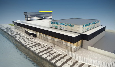
Exhibition Centre Liverpool
![]()
Address: Kings Dock, Liverpool Waterfront, Liverpool
Developer: ACC Liverpool
Main Contractor: ISG
Architect: Corker Marshall
Structural Engineer: Booth King
MEP (Mechanical, Electrical & Public Health) Design & Build: Briggs & Forrester
Building Information and Statistics
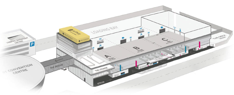
- 8100 m2 exhibition centre
- 3 main halls, Hall A = 60m wide x 45m long x 10.5m high, Hall B = 60m wide x 45m long x 10.5m high, Hall C = 60m wide x 45m long x extended 18m high
- Flexible design to utilise individual halls or combine two halls or all three
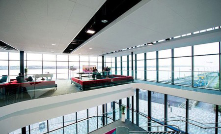
- Large Atrium area with catering outlets and facilities
- 8 interchangeable terrace suites overlooking the River Mersey ranging from 30m2 single suite up to 170m2 combined suites
- Integrated to the BT Convention Centre and Echo Arena via an interconnecting bridge
- Integrated 4 star 216 bedroom Pullman hotel
- Steel framed structure with concrete floors
- The hotel has a ground floor, reception, lounge, bar and restaurant. First floor has ACC office area and meeting rooms, the second floor has executive lounges, fitness centre and hotel rooms, the third to eighth floor has hotel rooms and the roof is a plantroom deck partly enclosed and partly exposed
Building Services General Description
- Service trench runs through the centre of all the exhibition halls with trenched services to pop ups throughout the halls to provide maximum flexibility
- Large plant deck to the West of the exhibition halls with 4 Air Handling Units per hall to provide comfort cooling via high level 1.8m diameter ducts
- Extract air from the halls is via 4No. 5m x 2.5m louvres on the West of the halls which is extract back to the Air Handling Units and the heat is reclaimed
- The building is installed with a syphonic rain water system
- The main mechanical plantroom is situated South of hall C on level 2 and contains all the boilers, pumps and domestic water heaters
- The water tankroom is located East of hall C on the ground floor and provides all the domestic water
- The hotel has 216 bedrooms which are all fitted with individual fan coil units to provide comfort cooling to each room
- Each of the hotel rooms has a bathroom pod with vertical MEP distribution risers behind each pod, domestic services are fed from level one upwards and the mechanical pipework and ventilation is fed from the roof downwards
- The hotel mechanical plantroom is located on the roof plant deck and the domestic water tankroom is located within the ECL building at level 1 East of hall A
BIM (Building Information Modelling) Objectives
- Increase quality of co-ordinated design information, eliminating design conflicts prior to construction
- Increase collaboration between design disciplines
BIM Scope
- Although the project had no specific BIM requirements our client was keen to utilise the basics of BIM to ensure a successful installation
- 3D virtual model all MEP services
- 3D virtual model all certified / procured plant and equipment
- 3D virtual model all MEP services bracketry on the main plant deck to provide a goal post type access way to maintain and inspect all plant equipment
- 3D virtual model all anchor and expansion devices
- 3D virtual model all access zones to demonstrate access to all maintainable plant, equipment and access points, such as rodding eyes
- 3D virtual model all builderswork sleeves
- Co-ordinate and clash detect all MEP services with structure, architecture and all other trade contractors
- Produce 2D installation quality drawings for all MEP services, fully notated and dimensioned in x, y & z planes
- Produce 2D builderswork drawings for all plinth requirements and all structure and building fabric penetrations
- Manage the EDMS (Electronic Data Management System) for the uploading and downloading of models, drawings, technical submittals and RFI’s (request for information)
- Producing progress reports and attending / chairing bi-weekly BIM review meetings
Summary
The BIM process took place prior to construction and proved to be very successful. All building fabric openings for MEP services were created within the model and transposed into 2D drawings for the use of the construction team, this ensured no additional costs for returning to constructed walls to create openings. At the outset of the project there was 2 main plant decks to house the main air handling units, these were located on both the East and West of the halls. With the use of BIM we were able to model all the air handling units and associated services onto one plantroom deck on the West of the halls which created more usable space for the client on the East which was later transformed into additional catering facilities.